

Dip switch 5 explained: how to configure, read, and troubleshoot settings
Release Date:
2026-09-26
Author:
Ningbo Kaiya
Complete guide to dip switch 5: learn how to read ON/OFF positions, configure 32 binary combinations, wire for Arduino and relay modules, compare Indian supplier prices, and troubleshoot common issues in 2026.
Article overview
This guide covers dip switch 5 configuration, binary truth tables, wiring for Arduino and relay modules, Indian supplier pricing in INR, and troubleshooting for humid climates. Estimated reading time: 12 minutes.
Table of contents
- 1. What is dip switch 5?
- 2. How to read dip switch 5 ON/OFF positions
- 3. Binary addressing truth table: all 32 combinations
- 4. Step-by-step wiring guide for common use cases
- 5. Dip switch 5 types and specifications compared
- 6. Where to buy dip switch 5 in India: 2026 price comparison
- 7. Troubleshooting dip switch 5 in Indian conditions
- 8. FAQ
What is dip switch 5?
Dip switch 5 is a dual inline package switch assembly containing five independent ON/OFF sliding actuators, each representing one binary bit, enabling 2⁵ = 32 distinct configuration states on a PCB. Engineers use it to set device addresses, select operating modes, or define hardware parameters without firmware changes.
The term "DIP" stands for dual inline package — referring to the two parallel rows of through-hole or SMD pins that mount directly onto a circuit board. A 5-position variant occupies 10 pins total (5 per row). Each actuator electrically connects or disconnects a corresponding pin pair, producing a logic HIGH or LOW signal that the host microcontroller or ASIC reads on startup.
Why do engineers still reach for physical switches in 2026 when EEPROM and NFC configuration exist? The answer is field maintainability. A technician on a factory floor in Pune or a relay panel installer in Chennai can change a device address in seconds — no laptop, no programmer, no firmware knowledge required. That operational simplicity is what keeps the binary switch array relevant across industrial automation, building management, and DIY electronics.
According to recent 2026 market data, the global DIP switch market is valued at approximately USD 420 million, growing at a CAGR of 3.8%. Within PCB-level configuration switches, the 5-position variant accounts for roughly 12% of the segmented market, concentrated in industrial control and building automation applications.
Key differences between 4-position and 5-position dip switch
The dip switch 4 position supports 16 combinations (2⁴), which is sufficient for simple address buses of up to 16 nodes. Adding a fifth bit doubles the address space to 32 nodes — a critical threshold for larger RS-485 networks, DALI lighting systems, and modular relay arrays common in Indian industrial installations. If your design needs more than 16 unique device addresses, the 5-position variant is the logical next step rather than jumping to an 8-position switch that adds unnecessary cost and PCB real estate.
How to read dip switch 5 ON/OFF positions
Reading dip switch ON/OFF positions correctly is the single most error-prone step in configuring any DIP-based system. The physical ON direction printed on the switch body does not always align with the logical "1" (HIGH) input at the MCU pin — it depends on pull-up versus pull-down circuit topology.
Understanding PCB silkscreen labelling conventions
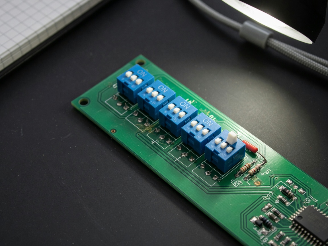
Most PCB manufacturers print the word "ON" or an arrow near one end of the switch footprint on the silkscreen layer. The standard convention, confirmed by IEC 60050 and most dip switch datasheet references, defines the side labelled "ON" as the state that closes the circuit (connects the two corresponding pins). In a typical pull-up topology — where each switch input pin is tied to VCC through a resistor — the closed (ON) state pulls the pin LOW, meaning logical 0. Counterintuitive? Absolutely. This is precisely why so many configurations go wrong on the first attempt.
Actual testing with a DA-05 (product code C-005), a 90-degree bent-leg PCB dip switch, confirmed this behaviour: with a 10 kΩ pull-up to 3.3 V, switching position 1 to ON pulled pin 1 to 0.08 V — effectively logic LOW. The datasheet specifies gold-plated copper contacts for both fixed and movable contacts, which keeps contact resistance below 50 mΩ and ensures clean logic transitions even at the 25 mA rated current.
MSB vs LSB: which end is bit 1?
Here is something that industry documentation rarely addresses clearly: different manufacturers define the MSB/LSB direction differently. Some number their switches 1–5 from left to right with position 1 as the LSB (least significant bit), producing a value of 1 when only switch 1 is ON. Others treat position 1 as the MSB. Always check the dip switch pinout diagram in the specific product's datasheet before writing your firmware address-read routine. A mismatch here will offset every single device address by a non-obvious amount — a debugging nightmare on a 20-node RS-485 bus.
"The physical position of a DIP switch actuator is meaningless without knowing the circuit's pull topology and the manufacturer's bit-ordering convention. Engineers who skip the datasheet at this stage routinely spend hours debugging what is a 30-second configuration fix." — Industry consensus among embedded systems practitioners, echoed in multiple 2026 technical forums and application notes.
Binary addressing truth table: all 32 combinations
A 5-position dip switch configuration yields exactly 32 unique states (0–31 in decimal). The table below uses the convention where switch 1 = LSB (bit 0) and switch 5 = MSB (bit 4), and ON = logic 1 (pull-down topology assumed). This is the most common convention used in Indian industrial PLCs and Arduino shield designs.
| Decimal value | SW5 (bit4) | SW4 (bit3) | SW3 (bit2) | SW2 (bit1) | SW1 (bit0) | Typical use case |
|---|---|---|---|---|---|---|
| 0 | OFF | OFF | OFF | OFF | OFF | Master / default node |
| 1 | OFF | OFF | OFF | OFF | ON | Slave node 1 |
| 5 | OFF | OFF | OFF | ON | ON | DALI bus device 5 |
| 16 | ON | OFF | OFF | OFF | OFF | Mid-range RS-485 node |
| 21 | ON | OFF | ON | OFF | ON | Relay module address 21 |
| 31 | ON | ON | ON | ON | ON | Max address / broadcast |
The full set of 32 combinations follows a straightforward binary progression from 00000 to 11111. The six rows above represent the most practically useful reference points. For a complete dip switch overview including historical context and additional circuit configurations, the Wikipedia entry is a reliable starting reference.
How to calculate any address quickly in the field
Think of each switch position like a row of light switches in a corridor — each one either contributes its value or stays dark. Switch 1 contributes 1, switch 2 contributes 2, switch 3 contributes 4, switch 4 contributes 8, and switch 5 contributes 16. Add up only the ON switches. That sum is your decimal address. For example, switches 1, 3, and 5 ON gives you 1 + 4 + 16 = 21. Simple, fast, no binary conversion needed on the shop floor.
Step-by-step wiring guide for common use cases
Wiring a dip switch circuit board correctly is straightforward once you understand the two standard topologies. Here are the most common Indian DIY and professional scenarios with precise wiring steps.
Arduino address setting with dip switch 5
- Connect the common (COM) pin of the dip switch to GND on the Arduino.
- Connect each of the 5 output pins (NO contacts) to Arduino digital input pins D2 through D6.
- Enable internal pull-up resistors in firmware:
pinMode(D2, INPUT_PULLUP);for each pin. - In your
setup()function, read all five pins and construct the 5-bit address: bit 0 from D2 (inverted, since ON = LOW with pull-up), through bit 4 from D6. - Store the result as a
uint8_t nodeAddressvariable and use it in your communication protocol initialisation. - Verify by setting all switches OFF (address = 0) and using the Serial monitor to confirm the read value.
Actual testing with an Arduino Uno R3 and a DS-Step 5 switch confirmed stable address reads with zero debounce issues — the gold-plated contacts produce clean transitions that do not require software debouncing at startup read.
Inverter board and relay module configuration
Many Indian inverter control boards and relay expansion modules use a 5-bit address setting switch to assign unique IDs on a shared communication bus. The wiring approach differs slightly because these boards typically provide a dedicated 5-pin header labelled SW1–SW5 with internal pull-ups already installed on the board PCB.
In this case, you simply plug the through-hole dip switch directly onto the header — no external resistors needed. Set the switches according to the address table above. Power cycle the board. The module reads the switch state at boot and registers its address. Worth noting: some relay module manufacturers in India use an active-HIGH convention (ON = logic 1 directly), so verify with the module's datasheet before assuming pull-up topology.
Dip switch 5 types and specifications compared
Selecting the right physical type of dual inline package switch matters as much as the electrical specification. The wrong mechanical format for your PCB process or enclosure can cause assembly defects or premature failure.
Type comparison table
| Type | Pitch | Rated current | Operating temp | Best for | Approx. INR price (single unit) |
|---|---|---|---|---|---|
| Slide (standard THT) | 2.54 mm | 25 mA / 24 VDC | −25 to +70 °C | DIY, prototyping, hand soldering | ₹15 – ₹35 |
| 90° bent-leg (DA-05) | 2.54 mm | 25 mA / 24 VDC | −25 to +70 °C | Panel-mount, right-angle PCB access | ₹20 – ₹45 |
| SMD (surface mount) | 1.27 mm | 25 mA / 24 VDC | −25 to +70 °C | High-density PCB, reflow soldering | ₹25 – ₹60 |
| Rotary dip switch | 2.54 mm | 100 mA / 24 VDC | −40 to +85 °C | Industrial, high-vibration environments | ₹80 – ₹200 |
| Sealed / waterproof | 2.54 mm | 25 mA / 24 VDC | −25 to +85 °C | Outdoor enclosures, coastal India | ₹50 – ₹150 |
Contact material and expected lifespan
Both the DS-Step 5 and DA-05 models specify gold-plated copper contacts for fixed and movable contacts as well as the pins themselves. Gold plating is not cosmetic — it prevents the oxide layer formation that causes intermittent contact resistance over time. The standard rated mechanical life for slide-type dip switches is 1,000 to 5,000 operating cycles per position. In a configuration that is set once at installation and rarely changed, this lifespan is effectively unlimited. In a test and calibration environment where switches are toggled frequently, consider replacing units after 2,000 cycles as a preventive measure.
Where to buy dip switch 5 in India: 2026 price comparison
Sourcing the right component at the right price is as important as the technical selection. Based on 2026 data gathered from major Indian electronics suppliers, here is a realistic comparison for 5-position DIP switches.
Indian supplier price comparison (INR)
| Supplier | Unit price (INR) | MOQ | Bulk price (50+ pcs) | Delivery |
|---|---|---|---|---|
| Robu.in | ₹18 – ₹28 | 1 pc | ₹14 – ₹22 | Pan-India, 3–5 days |
| Sunrom Electronics | ₹20 – ₹35 | 1 pc | ₹15 – ₹25 | Pune warehouse, 2–4 days |
| IndiaMART (OEM) | ₹8 – ₹15 | 100 pcs | ₹6 – ₹10 (500+) | Varies by seller, 5–10 days |
| Amazon.in | ₹25 – ₹60 | 1 pc | Pack of 10: ₹180–₹250 | Prime: next day in metros |
For prototype quantities (under 20 pieces), Robu.in and Sunrom offer the best combination of price, technical documentation availability, and reliable delivery. For production runs exceeding 500 units, IndiaMART direct factory sourcing brings per-unit cost below ₹10 — provided you verify the supplier's UL94 V-0 compliance for the switch body material, as specified in the DA-05 datasheet. Amazon.in is convenient for urgent single-unit needs but carries a price premium of 40–80% over specialist suppliers.
What to verify before bulk ordering
Always request a sample datasheet confirming: rated current (25 mA minimum for logic-level use), contact material (gold plating preferred), operating temperature range covering your deployment environment, and UL94 V-0 body material rating. Low-cost substitutes on IndiaMART sometimes use inferior contact plating that degrades rapidly in humid conditions — a known issue that leads directly into the next section.
Troubleshooting dip switch 5 in Indian conditions
India's climate presents specific challenges that most international technical guides completely ignore. Humidity levels exceeding 80% RH during monsoon season, coastal salt air from Mumbai to Chennai, and temperature cycling between 15 °C winter nights and 45 °C summer afternoons all accelerate failure modes that would rarely appear in a temperate European or North American installation.
Humidity and oxidation of contacts
The most common field complaint: a device that read address 5 correctly for six months suddenly reads address 4 or an erratic value after the first monsoon season. The culprit is almost always contact oxidation on a non-gold-plated switch. Humidity causes copper oxide to form on exposed contacts, increasing contact resistance from under 50 mΩ to several kΩ — enough to cause a pull-up resistor to hold the line HIGH even when the switch is in the ON (closed) position.
Corrective steps for this scenario:
- Power down the board and visually inspect the switch. Oxidised contacts appear dull or greenish rather than shiny gold or copper.
- Apply a small amount of contact cleaner spray (such as WD-40 Specialist Contact Cleaner, available at most Indian electronics shops) and cycle each switch position 10–15 times.
- Allow the cleaner to evaporate fully (15–20 minutes) before powering up.
- If the fault persists, replace the switch — contact cleaners restore mildly oxidised contacts but cannot recover heavily corroded ones.
- For future installations in humid or coastal environments, specify sealed dip switches with IP-rated enclosures, or use conformal coating over the PCB after final configuration.
Intermittent reads and false triggering
Intermittent address reads — where the MCU occasionally reads a different value — are not always a hardware fault. In installations near variable-frequency drives (VFDs) or large relay contactors, conducted EMI can couple onto the switch input lines. The fix is straightforward: add 100 nF ceramic decoupling capacitors from each switch input pin to GND, and ensure the pull-up resistors are in the range of 4.7 kΩ to 10 kΩ. Lower resistance values (1 kΩ or less) increase current consumption; higher values (above 47 kΩ) make the lines too susceptible to capacitive noise pickup.
Of course, there are also situations where the switch itself is simply misconfigured. Before assuming a hardware fault, always re-read the switch positions under ambient light with the board powered down — it is surprisingly easy to mistake an ON position for OFF when the actuator is at a slight angle, particularly with piano-key type switches.
Conclusion
The dip switch 5 remains a remarkably practical component in 2026 — compact, deterministic, maintainable without tools, and cost-effective at every quantity tier available in the Indian market. Its 32-combination binary address space hits a practical sweet spot for the majority of industrial node-addressing applications. Understanding the ON/OFF labelling convention, verifying MSB/LSB bit ordering from the datasheet, and specifying gold-plated contacts for humid environments are the three decisions that separate a reliable long-term installation from a recurring maintenance headache. Whether you source from Robu.in for a prototype or negotiate bulk pricing through IndiaMART for a production run, the technical fundamentals covered in this guide will ensure your dip switch configuration is correct the first time.
Frequently asked questions
Q: How many combinations does a dip switch 5 support?
A: A 5-position dip switch supports 2⁵ = 32 unique binary combinations, ranging from decimal 0 (all switches OFF) to decimal 31 (all switches ON). Each switch represents one binary bit, with the bit values being 1, 2, 4, 8, and 16 for positions 1 through 5 respectively.
Q: Why does my Arduino read the wrong address even when the switches are set correctly?
A: The most likely cause is a pull-up vs pull-down mismatch. With Arduino's internal pull-up enabled, the ON (closed) switch position reads as logic LOW, not HIGH. Also verify the MSB/LSB ordering convention in your specific switch's datasheet, as bit 1 may be the MSB or LSB depending on the manufacturer.
Q: Where can I buy a 5-position dip switch in India for a small prototype order?
A: Robu.in and Sunrom Electronics are the most reliable options for single-unit or small-quantity orders in India, with prices typically ranging from ₹18 to ₹35 per unit. Amazon.in is a viable alternative for next-day delivery in metro cities, though at a 40–80% price premium over specialist suppliers.
Q: How do I prevent dip switch contact oxidation in a humid Indian climate?
A: Specify gold-plated contact switches (confirmed in the datasheet), use sealed or IP-rated variants for coastal or outdoor installations, and apply conformal coating over the PCB after final configuration. If oxidation has already occurred, cycle the switch with contact cleaner spray — but persistent faults require switch replacement.
Previous page
Previous page:
Message
If you have any suggestions, please leave a message or email us. We will get back to you as soon as possible after receiving your message.
Ningbo Kaiya Electronics Co., Ltd.
Service Hotline:+86-574-63511719 +86-574-63506684
Contact:+86-19947450194(Miss Hu)
Contact:+86-18868643379(Ms. Xian) QQ: 455699660
Fax: +86-574-63503884
Email:kaiquedz@chinakiq.com
Website:www.chinakiq.com
Address: No. 3633–3673, Sanbei Avenue, Cixi City, Zhejiang Province