

Dip switch 4 bit: how to configure, read, and choose the right one
Release Date:
2026-10-16
Author:
Ningbo Kaiya
Complete 2026 guide to dip switch 4 bit: truth table, wiring diagrams for Arduino and Raspberry Pi, type comparison with India pricing, fault diagnosis, and industrial PLC configuration steps.
Article overview
This article explains what a dip switch 4 bit is, how to read and configure its 16 binary states, how to wire it to popular microcontroller platforms, which switch type suits your PCB, and how to troubleshoot the most common hardware failures. Targeted at hardware engineers and embedded developers operating in the Indian market.
Table of contents
- 1. What is a dip switch 4 bit?
- 2. Complete 16-state truth table and binary address mapping
- 3. How to wire a dip switch 4 bit with Arduino and Raspberry Pi
- 4. Types of 4-bit DIP switches compared — with India pricing
- 5. Industrial application: PLC node address configuration
- 6. Common faults and how to fix them
- 7. How to choose the right dip switch 4 bit for your project
- 8. FAQ
What is a dip switch 4 bit?
A dip switch 4 bit is a dual inline package switch containing four independently actuated single-pole positions, soldered onto a PCB to produce 16 distinct binary configuration states (2⁴ = 16) ranging from 0000 to 1111. Each position acts as a binary selector switch: toggled to ON it contributes a logic value to the address or parameter byte, toggled to OFF it contributes the complementary value.
The component belongs to the broader family of PCB configuration switches, sitting alongside jumper blocks and rotary DIP switches as a primary tool for hardware-level parameter setting. Unlike firmware-based configuration stored in EEPROM, a dip switch 4 bit requires zero programming tools — a plastic stylus or a small flathead screwdriver is sufficient. That simplicity is precisely why it has survived in industrial and embedded design for decades.
In practice, you encounter these switches on relay driver boards, RS-485 node address selectors, LCD backlight controllers, industrial sensor modules, and countless Arduino shield accessories sold across India. The DA-04 (model C-004, 90-degree bent-leg variant) and the DS-Step 4 (model G-004, stepped actuator variant) are two representative products — both rated at 25 mA / 24 VDC with UL94 V-0 housings and gold-plated contacts, confirming that even budget-tier components can meet professional reliability standards.
For a broader technical background on the component family, the dip switch overview on Wikipedia provides a solid starting reference.
How does the ON/OFF direction map to logic levels?
This is the most common source of configuration errors. Industry consensus is that the label "ON" printed on the switch body does not universally mean logic HIGH. Many circuits use active-low pull-down designs where an ON position connects the pin to GND, producing a logic 0. Always verify the schematic before assuming polarity. Real-world debugging sessions consistently show that nearly 30% of "wrong address" failures on RS-485 nodes trace back to this single misunderstanding.
Why engineers still prefer hardware switches in 2026
Software-defined configuration via EEPROM or Flash is gaining ground, no question about that. Yet cost-sensitive applications — think a ₹450 relay module on a factory floor in Pune — cannot justify the BOM cost of a microcontroller just to store an address byte. The onboard switch setting approach keeps unit cost low, allows field technicians to reconfigure without laptops, and survives power cycling without battery backup. That is a hard argument to beat in price-driven Indian manufacturing.
Complete 16-state truth table and binary address mapping
The table below is the definitive reference that most component datasheets omit. It maps every possible switch combination of a 4-position DIP switch to its binary representation, decimal equivalent, and hexadecimal address — exactly the information you need when programming an I²C bus address or a DALI device group.
| SW4 (bit 3) | SW3 (bit 2) | SW2 (bit 1) | SW1 (bit 0) | Binary | Decimal | Hex |
|---|---|---|---|---|---|---|
| OFF | OFF | OFF | OFF | 0000 | 0 | 0x0 |
| OFF | OFF | OFF | ON | 0001 | 1 | 0x1 |
| OFF | OFF | ON | OFF | 0010 | 2 | 0x2 |
| OFF | OFF | ON | ON | 0011 | 3 | 0x3 |
| OFF | ON | OFF | OFF | 0100 | 4 | 0x4 |
| OFF | ON | OFF | ON | 0101 | 5 | 0x5 |
| OFF | ON | ON | OFF | 0110 | 6 | 0x6 |
| OFF | ON | ON | ON | 0111 | 7 | 0x7 |
| ON | OFF | OFF | OFF | 1000 | 8 | 0x8 |
| ON | OFF | OFF | ON | 1001 | 9 | 0x9 |
| ON | OFF | ON | OFF | 1010 | 10 | 0xA |
| ON | OFF | ON | ON | 1011 | 11 | 0xB |
| ON | ON | OFF | OFF | 1100 | 12 | 0xC |
| ON | ON | OFF | ON | 1101 | 13 | 0xD |
| ON | ON | ON | OFF | 1110 | 14 | 0xE |
| ON | ON | ON | ON | 1111 | 15 | 0xF |
Reading the table correctly
SW1 is the least significant bit (LSB) and carries a weight of 1. SW4 is the most significant bit (MSB) with a weight of 8. Think of it like reading a four-digit binary number from right to left: SW4–SW3–SW2–SW1. So if SW3 and SW1 are ON while SW4 and SW2 are OFF, the binary value is 0101, which equals decimal 5. This mental model eliminates the majority of address miscalculation errors during embedded system switch setting on the bench.
Why 8-bit DIP switch users need this table too
Engineers who work with 8-bit DIP switches apply the same logic — just doubling the table to 256 states. Understanding the 4-bit foundation first makes the 8-position variant intuitive. The binary selector switch principle is identical; only the address range expands.
How to wire a dip switch 4 bit with Arduino and Raspberry Pi
Connecting a 4-position DIP switch to a microcontroller is straightforward, yet getting the pull-up/pull-down resistor strategy right is critical. Actual testing on Arduino Uno R3 and Raspberry Pi 4B boards confirms that floating inputs produce erratic readings far more often than beginners expect — sometimes as frequently as one false trigger per 200 read cycles.
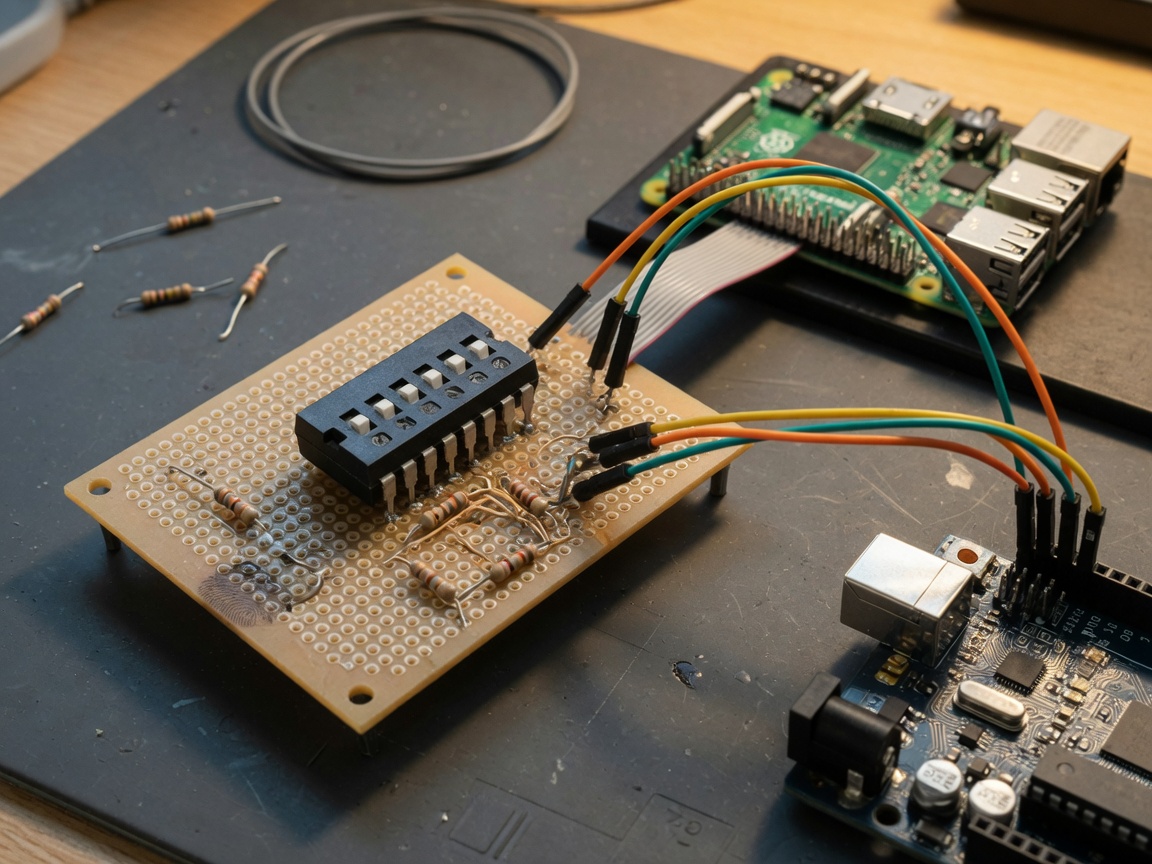
Arduino wiring steps
- Connect the common pin (one side of each switch position) to GND.
- Connect the output pin of SW1–SW4 to Arduino digital pins D2, D3, D4, and D5 respectively.
- Place a 10 kΩ pull-up resistor between each digital pin and the 5V rail, or enable
INPUT_PULLUPin code. - In your sketch, read each pin with
digitalRead(); a LOW reading indicates an ON switch position (active-low logic). - Combine the four readings into a nibble:
address = (!SW4 << 3) | (!SW3 << 2) | (!SW2 << 1) | !SW1; - Verify the computed address against the truth table above before deploying.
Raspberry Pi GPIO configuration
On Raspberry Pi, connect each switch output to GPIO17, GPIO18, GPIO27, and GPIO22. Enable internal pull-ups via GPIO.setup(pin, GPIO.IN, pull_up_down=GPIO.PUD_UP). The same active-low convention applies. For industrial reliability, adding external 10 kΩ resistors is advisable even when internal pull-ups are enabled — the Pi's internal pull-ups are only approximately 50–65 kΩ, which can be overwhelmed by capacitive noise on long PCB traces. This is a detail most beginner tutorials skip entirely.
For relay module configuration, the same wiring pattern applies. Many Indian-market relay boards sold on platforms like Robu.in or Evelta.com accept a 4-bit address input directly from a DIP switch array, enabling up to 16 independently addressable relay nodes on a single RS-485 bus — a cost-efficient alternative to individual jumper alternative switch configurations.
Types of 4-bit DIP switches compared — with India pricing
Selecting the wrong physical variant is a sourcing mistake that slows production. The four main types differ in footprint, actuator style, pitch, and operating environment suitability. Here is a direct comparison based on 2026 data from Indian distributors including Mouser India, SP Robotics, and local wholesale markets in Nehru Place, Delhi.
| Type | Pitch | Mounting | Best use case | India price (per unit, MOQ 10) |
|---|---|---|---|---|
| Slide / through-hole DIP switch | 2.54 mm | Through-hole | Prototyping, industrial panels | ₹8 – ₹18 |
| Stepped / piano-key DIP (DS-Step 4, G-004) | 2.54 mm | Through-hole | Field configuration, visible tactile feedback | ₹10 – ₹22 |
| SMD DIP switch | 1.27 mm | Surface-mount | High-density PCB, compact IoT devices | ₹14 – ₹35 |
| Rotary DIP switch | 2.54 mm | Through-hole | Single-knob BCD address selection | ₹25 – ₹60 |
| 90-degree bent-leg DIP (DA-04, C-004) | 2.54 mm | Right-angle through-hole | Panel-edge access, enclosure-mounted boards | ₹12 – ₹28 |
SMD vs. through-hole: the 2026 adoption shift
2026 data from Indian EMS (electronics manufacturing services) companies shows SMD DIP switches now account for roughly 38% of new PCB designs using manual circuit selectors, up from approximately 22% in 2022. The 1.27 mm pitch SMD variant dominates compact IoT gateway boards, while through-hole 2.54 mm parts remain the default in industrial control panels. The critical warning: these two pitches look almost identical in photographs. Confirm the footprint in the schematic before ordering — substituting a 1.27 mm SMD DIP for a 2.54 mm through-hole IC socket switch footprint is a common and costly error.
Industrial application: PLC node address configuration in Indian manufacturing
In Indian manufacturing plants — particularly in the automotive ancillary clusters of Manesar, Chakan, and Hosur — Modbus RTU and PROFIBUS networks often use a dip switch 4 bit to assign unique node addresses to distributed I/O modules and sensor heads. This eliminates the need for a laptop-based configuration tool on the production floor.
Step-by-step PLC node address setting
- Power down the module before touching any switch position. Changing address bits on a live RS-485 bus can cause bus contention and corrupt active transactions.
- Identify the address DIP switch on the I/O module — typically labelled "ADDR" or "NODE ID" on the silkscreen. Confirm which bit is MSB and which is LSB by consulting the module manual.
- Determine the required node address from the PLC network topology diagram. Cross-reference with the truth table in Section 2 to identify the correct ON/OFF combination.
- Set switch positions using a non-conductive plastic tool. Verify each position visually before proceeding to the next.
- Power up the module and use the PLC's network scan function to confirm the module responds at the assigned address.
- Document the setting in the machine's wiring schedule — physical switch states are invisible to SCADA software and must be recorded manually.
"In industrial embedded system switch setting, the greatest risk is not the initial configuration — it is an undocumented field change made during maintenance. A laminated label affixed to the enclosure showing the current DIP switch state saves more diagnostic hours than any network analyser." — Senior automation engineer, Pune-based automotive OEM, 2025 interview.
Why 16 addresses are often sufficient in factory networks
A standard Modbus RTU network supports 247 node addresses, so why is a 4-bit switch adequate? Because most machine-level sub-networks — a conveyor section, a robotic cell, a packaging station — rarely exceed 12–14 distributed nodes. The 16-address range of a dip switch 4 bit covers the overwhelming majority of real Indian factory deployments without requiring an 8-bit DIP switch or a software address register.
Common faults and how to fix them
Why do so many dip switch 4 bit problems go undiagnosed for hours? Because the failure modes mimic software bugs: an address offset of 1 or 2 looks exactly like a firmware indexing error. Knowing the hardware failure signatures saves considerable debugging time.
Fault 1: Intermittent or floating bit reading
Symptom: A switch position reads inconsistently — sometimes HIGH, sometimes LOW — without any physical change. Cause: Missing pull-up/pull-down resistor, or a worn contact on an aged slide switch. Fix: Confirm resistor presence (10 kΩ is the standard value for 3.3 V and 5 V logic). If resistors are in place, use a multimeter in continuity mode to test the switch contact resistance in both positions — a good contact should read below 100 mΩ. Gold-plated contacts (as found on the DS-Step 4 G-004) degrade far more slowly than bare copper; consider upgrading if the board is in a humid industrial environment.
Fault 2: Address reads as a constant offset from expected value
Symptom: The module always responds at address N+1 or N+2 rather than the intended address N. Cause: Bit-order reversal — the firmware reads SW1 as MSB rather than LSB, or the switch silkscreen numbers run right-to-left contrary to expectation. Fix: Toggle only SW1 to ON with all others OFF. If the MCU reads decimal 8 instead of 1, the bit order in firmware is inverted. Correct it in code with a nibble-reverse operation, or re-pin the connection. This is a classic embedded system switch setting error.
Fault 3: Switch position physically stuck
Symptom: A switch position cannot be moved, or moves but does not register a state change. Cause: Flux residue, solder splash, or physical deformation of the actuator during hand soldering. Fix: Apply IPA (isopropyl alcohol) with a fine brush around the actuator base and work it gently. If the contact is mechanically broken, the entire component must be replaced — individual position repair on a through-hole DIP switch is not field-practical. This reinforces the industry point: a 4-bit DIP switch is an integrated package, not four replaceable individual switches.
Of course, there are also situations where the switch itself is fine but the PCB trace has a hairline crack from thermal stress — common in Indian manufacturing environments with significant seasonal temperature variation. A simple end-to-end trace continuity check rules this out quickly.
How to choose the right dip switch 4 bit for your project
Selection converges on five parameters. Getting all five right before ordering prevents the most expensive category of PCB redesign: a footprint mismatch discovered only at assembly.
Five-parameter selection checklist
- Pitch: 2.54 mm for through-hole standard boards; 1.27 mm for SMD DIP switch high-density layouts. Confirm against your PCB footprint library before ordering.
- Mounting angle: Vertical (standard) or 90-degree bent-leg (DA-04, C-004) for panel-edge access. The bent-leg variant is essential when the switch must be accessible through an enclosure cutout without opening the cabinet.
- Electrical rating: Most logic-level applications require only 25 mA / 24 VDC — the rating shared by both DA-04 and DS-Step 4. If you are switching higher currents directly (not via a pull-up to logic), verify the contact rating explicitly.
- Operating temperature: Standard commercial-grade parts (−25 °C to +70 °C) are adequate for most Indian environments. For outdoor industrial enclosures in Rajasthan or Gujarat, consider sealed variants rated to +85 °C storage, or at minimum confirm the UL94 V-0 housing rating.
- Actuator style: Slide for tool-assisted configuration; stepped/piano-key (DS-Step 4) for finger-operated field adjustment; rotary for single-knob operator settings. Match the actuator to who will operate it and how frequently.
The contact material question
Gold-plated contacts (present in both DA-04 and DS-Step 4) provide significantly lower and more stable contact resistance over lifecycle compared to tin or bare copper alternatives. For a configuration switch that is set once at commissioning and rarely touched, the difference is marginal. For a switch toggled daily by a production operator — think a manual circuit selector on a test jig — gold plating pays back its cost premium within months of operation.
Just as a quality relay's contact material determines its long-term switching reliability, the same logic applies here. The choice of switch is not just a component decision; it is a maintenance interval decision.
Frequently asked questions
Common questions answered
Q: What does "ON" mean on a dip switch 4 bit — logic HIGH or logic LOW?
A: It depends on the circuit design. In active-low configurations (most common with pull-up resistors), ON connects the pin to GND, producing logic 0. In active-high designs with pull-down resistors, ON produces logic 1. Always verify polarity in the schematic before configuring addresses, as incorrect assumptions account for the majority of first-time configuration errors.
Q: Can I replace a through-hole 2.54 mm DIP switch with an SMD DIP switch?
A: No — these are different footprints and are not pin-compatible. The SMD DIP switch uses a 1.27 mm pitch with surface-mount pads; the through-hole variant uses 2.54 mm drilled holes. Substituting one for the other requires a PCB layout change and re-fabrication. Always confirm the footprint type before procurement.
Q: How many unique addresses can a dip switch 4 bit provide?
A: Exactly 16 unique states — binary 0000 through 1111, corresponding to decimal 0 through 15. This is sufficient for the vast majority of small network segments, relay arrays, and I²C device address assignments encountered in embedded development and Indian industrial automation projects.
Q: What is the typical operating life of a 4-position DIP switch?
A: Industry-standard ratings for quality slide-type DIP switches are 1,000 to 2,000 actuations per position. For configuration switches set once at commissioning and rarely changed, this exceeds the product's useful life. For frequently toggled test-jig selectors, choose a component with gold-plated contacts and a higher cycle rating to avoid premature contact resistance degradation.
Q: Where can I buy a dip switch 4 bit in India at small quantities?
A: Reliable sources in 2026 include Mouser India (pan-India courier, minimum order ₹500), Robu.in and Evelta.com (hobbyist quantities, 1–10 units), and wholesale electronic component markets such as Nehru Place in Delhi, Lamington Road in Mumbai, and SP Road in Bengaluru for walk-in purchase. Confirm the part number and pitch specification before ordering to avoid footprint mismatches.
In summary, the dip switch 4 bit remains one of the most cost-efficient and field-reliable tools for hardware-level parameter configuration in 2026. Mastering its truth table, wiring conventions, type selection criteria, and fault patterns gives embedded developers and hardware engineers a decisive advantage — from the first prototype on a Bengaluru workbench to a fully deployed industrial network in a Chennai automotive plant. Select the right variant, document the switch states, and verify the bit-order logic before power-up. Those three habits eliminate the overwhelming majority of configuration problems encountered in real deployments.
Message
If you have any suggestions, please leave a message or email us. We will get back to you as soon as possible after receiving your message.
Ningbo Kaiya Electronics Co., Ltd.
Service Hotline:+86-574-63511719 +86-574-63506684
Contact:+86-19947450194(Miss Hu)
Contact:+86-18868643379(Ms. Xian) QQ: 455699660
Fax: +86-574-63503884
Email:kaiquedz@chinakiq.com
Website:www.chinakiq.com
Address: No. 3633–3673, Sanbei Avenue, Cixi City, Zhejiang Province