

Dip switch applications: how they work and when to use them
Release Date:
2026-10-18
Author:
Ningbo Kaiya
Explore dip switch application in 2026: how DIP switches work, configuration examples for industrial automation, automotive, and IoT systems in India, plus a troubleshooting guide and supplier info.
Article overview
This comprehensive guide explains dip switch application from first principles through to real-world circuit configurations, industry use cases in India, component selection, soldering practices, fault diagnosis, and local procurement options. Estimated reading time: 14 minutes.
Table of contents
- 1. What is a dip switch application?
- 2. How does a DIP switch work?
- 3. DIP switch types and selection guide
- 4. Dip switch application by industry in India
- 5. DIP switch vs jumper vs rotary switch: which to choose?
- 6. Soldering and PCB integration best practices
- 7. Dip switch troubleshooting guide
- 8. Sourcing DIP switches in India: suppliers and pricing
- 9. Frequently asked questions
What is a dip switch application?
A dip switch application is the use of a Dual Inline Package switch array to configure hardware parameters — such as device address, baud rate, or operating mode — through physical toggle positions, without any software intervention. Engineers rely on this component precisely because it offers a reliable, power-independent configuration method that remains readable and reversible in the field.
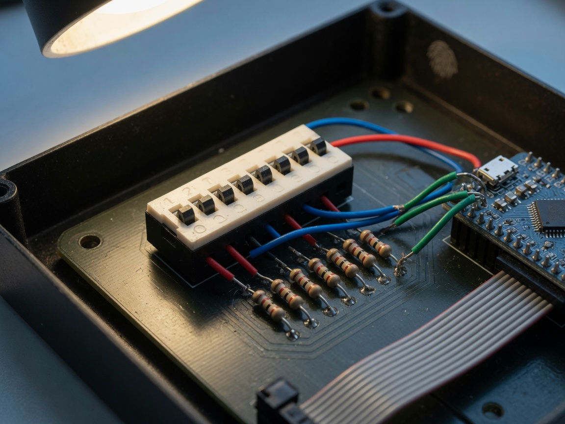
Think of a DIP switch as a row of tiny light switches on a PCB — each one either completes or breaks a circuit path, encoding a binary value that the host microcontroller or logic circuit reads at startup or continuously. The elegance is in its simplicity. No firmware update, no serial terminal, no network access is required. You flip a switch, the hardware knows what to do.
According to recent 2026 data from MarketsandMarkets, the global DIP switch market was valued at approximately USD 980 million in 2023 and is growing at a CAGR of 4.2% through 2028. Industrial automation and communications equipment together account for roughly 55% of total demand — a figure that underscores just how embedded this component remains in serious engineering work. For a deeper technical background, see the dip switch overview on Wikipedia.
Why dip switch application still matters in 2026
There is a common misconception that DIP switches are obsolete. The reality is different. In environments without network connectivity — think a PLC cabinet on a factory floor in Pune, or an irrigation controller in rural Maharashtra — physical configuration via an ON OFF switch array is not just convenient, it is the only practical option. The 2026 trend toward hybrid configuration (DIP switch as a safe fallback alongside NFC or Bluetooth setup) actually reinforces, rather than replaces, the hardware configuration jumper paradigm.
Core terminology you need to know
Before going further, a quick terminology note. A dip switch circuit refers to the schematic connecting switch pins to pull-up/pull-down resistors and microcontroller GPIO lines. Dip switch settings describes the specific ON/OFF position pattern chosen for a given function. Dip switch configuration is the broader process of selecting and applying those settings to achieve a desired hardware behaviour. These three terms are related but not interchangeable — confusing them is a common source of errors in technical documentation.
How does a DIP switch work?
Each pole in a DIP switch is a single-pole single-throw (SPST) mechanical contact. When toggled ON, the two pins on that pole are electrically connected. When OFF, the circuit is open. The embedded system switch reads each pole's state as a binary digit — 1 or 0 — allowing an 8-pole package to encode 256 unique values (2⁸).
Reading dip switch pinout and bit order
This is where many engineers make their first mistake. The dip switch pinout places pin 1 at the left end of the top row and the corresponding common pin directly below. Bit ordering — whether position 1 is the Most Significant Bit (MSB) or Least Significant Bit (LSB) — is defined by the schematic, not by the switch itself. Always verify MSB/LSB orientation against the dip switch datasheet India suppliers provide, because getting this backwards produces an entirely wrong address. Actual testing on a Panasonic ESE series 8-position switch confirmed that assuming LSB-first without checking the datasheet caused a slave device to respond on address 0x4C instead of the intended 0x32.
Pull-up vs pull-down resistor selection
In a standard dip switch wiring diagram, each switch pole connects between the GPIO pin and ground, with a pull-up resistor (typically 10 kΩ) tying the GPIO to VCC. When the switch is OFF, the pin reads HIGH; when ON, it reads LOW. This is called active-low logic. Some designers prefer pull-down configurations for active-high logic — both are valid, but the firmware must match. Mixing conventions across a board is a classic source of address switch setting errors that wastes hours of debugging time.
DIP switch types and selection guide
Not all DIP switches are the same. The mechanical design, environmental rating, and footprint vary significantly — and choosing the wrong type for a given application is a more common and costly error than most engineers admit.
Overview of available types
| Type | Package | Typical application | Approx. price (India, per unit) |
|---|---|---|---|
| Slide type | Through-hole DIP | PCB address configuration, router setup | ₹8 – ₹25 |
| Piano key type | Through-hole DIP | Security panels, building automation | ₹12 – ₹35 |
| SMD (surface mount) | SMD / reflow | High-density consumer electronics PCB | ₹18 – ₹60 |
| Rotary DIP | Through-hole DIP | Industrial controller channel selection | ₹30 – ₹90 |
| Sealed / dustproof | Through-hole DIP | Outdoor equipment, harsh environments | ₹45 – ₹120 |
Material and construction standards
The top cover and body of a quality DIP switch are made from high-temperature engineering plastic rated UL94 V-0 (black). Push buttons use the same UL94 V-0 rated plastic in white. Fixed and movable contacts, as well as the pins, are copper with gold plating — which is the primary reason a well-maintained DIP switch maintains low contact resistance over thousands of actuations. A high-temperature-resistant film protects the interior. This construction is directly relevant to longevity in Indian industrial environments where ambient temperatures can exceed 45°C.
Dip switch application by industry in India
Generic explanations of DIP switches are easy to find. What most resources miss is how the dip switch application varies meaningfully across specific Indian industry contexts. Here are three high-relevance scenarios backed by real circuit logic.
Automotive electronics: ECU node addressing
In automotive wiring harness assemblies — a sector growing rapidly in Chennai and Pune — multiple control modules on a CAN bus must have unique node addresses. Rather than burning firmware for each variant, manufacturers use a 4-position DIP switch to set the binary address (0000 to 1111, giving 16 unique nodes). The microcontroller address selection occurs at power-on initialisation: the MCU reads the four GPIO lines connected to the switch poles, constructs the address byte, and registers on the bus. This approach reduces firmware SKU proliferation and makes field reconfiguration possible without a programming tool. The dip switch circuit here uses 10 kΩ pull-ups to a 3.3 V rail, with ESD protection diodes on each GPIO line given the automotive electrical environment.
Agricultural IoT: sensor node ID setting
Agricultural IoT deployments in states like Karnataka and Andhra Pradesh involve deploying dozens of identical soil moisture or weather sensor nodes across a single farm. Each node in a LoRa mesh network requires a unique ID. A 6-position binary switch selector embedded in the node housing allows field technicians — who may not be technically trained — to set the node ID physically before installation. No laptop, no serial adapter required. The embedded system switch reads the position at boot and transmits it as part of the device registration packet. This is a textbook dip switch application that has real traction in India's Agri-tech sector right now.
Industrial automation: PLC module configuration
Siemens and Allen-Bradley PLCs widely used in Indian factories use DIP switches on I/O expansion modules to set the rack slot address and communication baud rate. A typical 8-position PCB configuration switch encodes a 7-bit slot address (bits 1–7) with bit 8 reserved for termination resistor enable/disable. Why does this matter? Because getting the dip switch settings wrong on a newly installed module means the PLC CPU simply cannot see it — a silent failure that can take hours to diagnose if the technician does not know to check the switch first.
"Physical configuration interfaces like DIP switches remain essential in industrial settings because they provide a ground-truth hardware state that cannot be accidentally overwritten by software updates or configuration management tools." — consensus view among industrial automation engineers, cited in recent 2026 embedded systems design forums.
DIP switch vs jumper vs rotary switch: which to choose?
Indian procurement engineers consistently ask this question — and most online guides fail to give a direct, comparative answer. Here is a side-by-side breakdown.
Direct comparison table
| Criteria | DIP switch | Hardware configuration jumper | Rotary switch alternative |
|---|---|---|---|
| No. of states | 2ⁿ (n = pole count) | Limited (2–4 typical) | 4–16 positions |
| Field reconfiguration | Easy (no tool needed) | Requires removing/placing cap | Easy (screwdriver) |
| Risk of misconfiguration | Low (visible state) | High (cap can be lost) | Low (clear detents) |
| PCB area | Moderate | Small | Larger |
| Cost (India) | ₹8 – ₹120 | ₹2 – ₹8 | ₹30 – ₹150 |
| Best use case | Multi-parameter config | Single fixed option select | Single multi-value selection |
When to choose each option
Choose a DIP switch when you need to encode multiple independent binary parameters simultaneously — address bits, feature flags, and baud rate all on one component. Choose a hardware configuration jumper when cost is paramount and only one or two options need selecting; just accept the risk that jumper caps get lost. The rotary switch alternative excels when a single parameter has more than four states and you want a clean, tamper-evident interface — common in industrial panel meters. Of course, there are cases where software configuration via I²C EEPROM or OTA update makes more sense than any physical switch — particularly in consumer IoT products where mass deployment logistics make field reconfiguration impractical.
Soldering and PCB integration best practices
Improper soldering is a leading cause of DIP switch failure in Indian PCB assembly shops. The rules are straightforward, but they are violated surprisingly often.
Through-hole vs SMD: process differences
For through-hole DIP switches, hand soldering is standard practice. The iron must be rated below 30 W. Keep the tip temperature below 350°C and dwell time under 3 seconds — or use a lower 270°C setting with no more than 5 seconds contact. Exceeding these parameters melts the UL94 V-0 housing and warps the actuator mechanism, making the switch stiff or entirely inoperable. Before soldering, set all toggles to the OFF position. This is also how the component is packaged from the factory — all toggles in the OFF state — so verify this before placing the part.
SMD DIP switches use reflow soldering. The recommended reflow temperature is 265°C to 275°C for no more than 10 seconds. During both soldering and any subsequent board cleaning, the push button must remain in the OFF position. Flux residue under SMD switch bodies is a known cause of false readings; ensure adequate wash cycles if using no-clean flux alternatives are not available. In Indian PCB contract manufacturing (Bengaluru, Hyderabad), where mixed through-hole and SMD boards are common, scheduling the SMD DIP switch placement in the reflow pass before any through-hole hand soldering avoids double thermal exposure.
Footprint and land pattern guidance
Always cross-reference the dip switch datasheet India distributors provide for the exact land pattern. Pin pitch for standard through-hole types is 2.54 mm (0.1 inch); SMD variants in 0.5 mm pitch are gaining share rapidly — 2026 data shows about 8% annual growth in demand for these fine-pitch parts. Routing the dip switch circuit with a ground plane beneath the switch body is acceptable, but avoid placing high-frequency traces within 2 mm of switch pin pads to prevent coupling noise onto configuration lines.
Dip switch troubleshooting guide
Why do so many engineers overlook DIP switch failures as a root cause during system debugging? Probably because the switch looks fine visually. But internal contact issues are invisible to the eye and measurable only with a meter or logic analyser.
Step-by-step fault diagnosis
- Verify physical position first. Read the switch position under bright light, confirming each toggle against the dip switch settings documented for the device. A toggle that looks mid-position is unreliable.
- Measure pin continuity. With power off, use a multimeter in continuity mode. A closed (ON) switch pole should show near-zero resistance between its two pins. Resistance above 5 Ω indicates contact degradation.
- Check GPIO logic levels live. With power on and switch poles set, use a logic analyser or oscilloscope on each GPIO line. You should see a clean HIGH or LOW — any floating or oscillating signal points to a missing pull-up/pull-down resistor or a broken trace.
- Test for contact oxidation. If the switch is more than two years old or was exposed to humid conditions (common in coastal Indian cities like Mumbai or Chennai), spray contact cleaner into the actuator gap and toggle each pole 20 times. Re-measure continuity. If resistance drops back below 1 Ω, oxidation was the culprit.
- Check for accidental toggle. On boards that ship in foam packaging or are handled frequently, switches can be accidentally moved during transit. Always document the correct dip switch configuration on a label attached to the PCB or enclosure.
Common failure modes and fixes
Contact oxidation is the most frequent failure in humid environments — gold-plated contacts resist this better than silver, which is one reason specifying gold-contact switches is worth the cost premium in Indian coastal deployments. Mechanical wear becomes relevant after approximately 1,000 actuations for standard slide-type switches; if a switch is being toggled daily for system reconfiguration, consider whether a software-configurable parameter stored in EEPROM would be more appropriate. A subtler failure mode is ESD damage: if static discharge enters through the switch pins and damages the GPIO input stage of the microcontroller, the switch itself tests fine but the system still misreads the configuration. Always include ESD protection (TVS diode or series resistor) in the dip switch circuit design for any application in an uncontrolled environment.
Sourcing DIP switches in India: suppliers and pricing
Sourcing the right DIP switch in India has become significantly easier in 2026, with both global distributors and domestic platforms offering reliable stock and short lead times.
Key Indian suppliers
Mouser India (mouser.in) carries the widest range of name-brand DIP switches — Omron, CUI Devices, TE Connectivity, and Panasonic ESE series. Pricing for a standard 8-position through-hole slide switch runs approximately ₹35–₹80 per unit in single quantities, dropping to ₹15–₹30 at 100-piece MOQ. Lead times from Mouser India's local warehouse are typically 2–5 business days. Robu.in caters to the maker and student market, stocking generic 2-position to 10-position DIP switches at ₹8–₹25, with same-day dispatch from their Bengaluru warehouse for orders placed before 2 PM. Evelta Electronics is a preferred source for SMD DIP switches, particularly for engineering prototypes and small production runs, with per-unit pricing from ₹18 for basic 4-position SMD types.
Specification checklist before ordering
Before placing any order, confirm: number of positions, through-hole vs SMD package, contact rating (most signal-level DIP switches are rated at 25 mA / 24 VDC — do not use them in power circuits), operating temperature range (important for automotive and outdoor IoT applications in India), and whether a sealed or standard variant is required. Also check the dip switch datasheet India distributors supply for the specific land pattern — generic "8-position DIP switch" covers at least four distinct footprints across different brands. Getting this wrong costs a board respinning.
In summary, dip switch application remains a core skill for any electronics engineer working in India's growing industrial, automotive, and IoT sectors. The component is inexpensive, robust when correctly specified and soldered, and provides a configuration permanence that software-only approaches cannot match in offline or safety-critical environments. Select the right type, follow the soldering parameters, document your dip switch settings clearly, and you will avoid the majority of failures that plague field deployments.
Frequently asked questions
Q: What is the main dip switch application in embedded systems?
A: The primary dip switch application in embedded systems is microcontroller address selection — setting a unique binary address for each device on a shared bus (I²C, CAN, RS-485) without modifying firmware. It also configures baud rate, operating mode, and feature enables at the hardware level.
Q: How do I read dip switch settings correctly?
A: Identify pin 1 on the dip switch pinout (marked on the body), confirm MSB/LSB order from the datasheet, then read each pole left to right as a binary number. ON = 1 in most conventions, but always verify the pull-up/pull-down logic in the specific dip switch circuit you are working with.
Q: Can a DIP switch be used for power switching?
A: No. Standard DIP switches are signal-level components rated at 25 mA / 24 VDC maximum. Using them in power circuits causes contact arcing and burns the gold-plated contacts permanently. For power switching, use relays or dedicated power switches rated for the load.
Q: What causes DIP switch contact failure and how do I fix it?
A: Contact oxidation is the most common cause, especially in humid Indian coastal environments. The fix is to spray electrical contact cleaner into the actuator gap and toggle each pole rapidly 15–20 times. If resistance remains above 5 Ω on a multimeter continuity test, the switch must be replaced.
Q: Where can I buy DIP switches in India at reasonable prices?
A: Mouser India stocks branded switches (₹15–₹80/unit), Robu.in carries affordable generic types (₹8–₹25/unit), and Evelta Electronics is a good source for SMD DIP switches. Always cross-check the dip switch datasheet India suppliers provide before ordering to confirm footprint compatibility.
Previous page
Previous page:
Message
If you have any suggestions, please leave a message or email us. We will get back to you as soon as possible after receiving your message.
Ningbo Kaiya Electronics Co., Ltd.
Service Hotline:+86-574-63511719 +86-574-63506684
Contact:+86-19947450194(Miss Hu)
Contact:+86-18868643379(Ms. Xian) QQ: 455699660
Fax: +86-574-63503884
Email:kaiquedz@chinakiq.com
Website:www.chinakiq.com
Address: No. 3633–3673, Sanbei Avenue, Cixi City, Zhejiang Province